
WHAT IS CORNEAL TOPOGRAPHY?
Corneal topography is the study of the shape of the corneal surface. Traditionally, such measurements were limited to the near-spherical central portion of the anterior corneal surface. With the advent of corneal refractive procedures, the necessity to study the more peripheral parts of the cornea and to understand better the optics of both the anterior and posterior corneal surfaces has spawned a number of new devices that allow the clinician to better understand corneal shape, power, and optical performance.
EVOLUTION OF CORNEAL TOPOGRAPHY
KERATOSCOPY:It is the evaluation of the corneal surface using circular mires reflected from its surface. The earliest device designed to perform this function was the PLACIDO’S DISC, developed by Antonio Placido. It consists of equally spaced alternating black and white rings with a hole in the centre to observe the patient’s cornea. The central opening houses a convex lens for magnification and to aid the examiner’s accommodation.
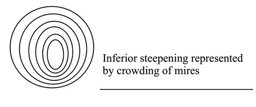
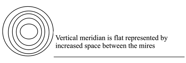
Given below are examples of images obtained from the reflection of the mires from the cornea.
 |
 |
Keratoscopes are devices with a self-illuminated set of concentric rings, like the Placido disc, and documentation of the obtained mire reflection can be done using a camera (PHOTOKERATOSCOPY) or a videocamera (VIDEOKERATOSCOPY). With advances in computing power, the addition of computers to the above devices has increased the amount of information that can be obtained and quantified from the reflected images. Apart from the qualitative assessment that is possible from the mire reflections, the use of algorithms to analyze the images results in large amounts of quantitative data that can be obtained virtually in real-time, with the powerful computers available today.
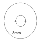
KERATOMETRY:The keratometer was invented by Helmholtz. It measures the radius of curvature of the anterior corneal surface from four points approximately 3 mm apart. However, its limitations are that the corneal apex and peripheral cornea are not taken into account, it assumes corneal symmetry, measures a variable area and is less accurate in very steep and very flat corneas, and treats the cornea as a spherocylindrical structure with two principal meridia separated by 90 degrees, resulting in errors in astigmatic axis measurement.
 |
RASTERSTEREOGRAPHYprojects a calibrated grid of horizontal and vertical lines 0.2 mm apart onto a fluorescein stained tear film and takes photograph and analyses the pictures for the displacement of the grid pattern.
INTERFEROMETRYuses the phenomenon of light wave interference. The fringes produced can cover the entire anterior ocular surface and not just the cornea.
ELEVATION BASED TOPOGRAPHY
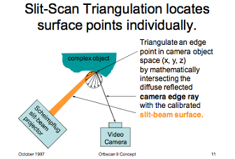
Slit scanning devices – These work on the Projection principle and measure surface elevation directly by slit-scan triangulation. Forty scanning slit beams (20 from the left and 20 from the right with up to 240 data points per slit) are used to scan the cornea from limbus to limbus and to measure independently the x, y, and z locations of several thousand points on each surface. In the newer version of the Orbscan® system, a placido disk has been mounted to this device in order to improve the accuracy of the curvature measurements.
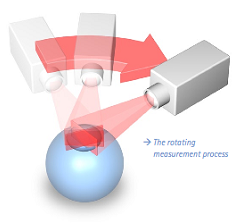
Scheimpflug Imaging - The Pentacam images the anterior segment of the eye using a rotating Scheimpflug camera and pictures in three dimensions of the anterior segment are shown by this rotating process. The images captured are then used to construct the anterior corneal surface, posterior corneal surface, and anterior iris and anterior lens surfaces.
WORKING PRINCIPLES OF COMMONLY USED SYSTEMS
All devices in use today comprise of 3 basic units or modules. There is an image acquisition device - which can either be a Placido disc-based tool, a slit-scanning instrument, or a Scheimpflug camera system. In some devices, more than one of these tools are utilized to obtain information - as mentioned later. The devices also have a camera to capture the images from the patient’s eye. Often, some kind of video display is built-in to monitor the patient’s eye prior to capture. The entire module is usually integrated along with a trigger for initiating image capture and the unit is placed on a stand that can be moved up and down to allow the patient to place his or her chin comfortably in the machine rest. There is also a processing computer that will analyze the data from the input device.
PROJECTION DEVICE:
Three types of projection devices are currently used. They all measure and analyze more than 8000 points.
1. PLACIDO –BASED SYSTEMS: These project a transilluminated disc or cone (modified Placido disc) onto the cornea surface and analyses the image reflected. Between 8- 32 concentric rings can be projected.
2. ELEVATION BASED SYSTEMS
3. SCHEIMPFLUG DEVICES
VIDEOCAMERA:
It captures the reflected image. Proper acquisition of data depends on focussing, decentration, good tear film quality.
COMPUTER:
It generates topographic maps based on the information collected.
Working Principle
Placido based devices
These work on the Reflection principle. The anterior surface of the cornea acts like a convex mirror and hence the size of the image formed by it is determined by its curvature. A steeply curved cornea will produce a smaller image, while a flatter cornea will produce a larger image – of the same object positioned at the same distance from the cornea. These devices thus, measure the slope of the cornea and compute the curvature. These work true to the principle of the Placido disc. They have different projection devices that use lighted circular rings of varying sizes and numbers. These rings are reflected by the convex patient cornea and through an opening in the center of the target, the images are obtained using an acquisition camera. The images are digitized, after allowing operator verification, and proprietary algorithms are used to determine the radius of curvature of the innermost ring. Once this is determined, the distance of the next reflected ring from the first ring is used to determine the curvature of this ring an so on – until the most peripheral ring is reached.
Usually, these values are determined for a finite number of points on the circle represented by each ring. Thus, the cornea between rings is not imaged and there is no actual data for these points. Thus, the apex of the cornea which is inside the innermost ring, is also not visualized or measured. Since reflection of images is a tear film based property of the cornea, in eyes which have irregularities of the corneal surface – or other tear film problems, distortion of the reflected images results in inaccurate estimation of corneal curvature.
Once the curvature of the points is determined, the corneal dioptric power at that point is determined using the formula -
Dioptric power of the Cornea = refractive index of cornea – refractive index of air / radius of curvature in meters = (1.376 – 1.0) / 7.6 x 10-3 = 49.45D
However, since the measured radius of curvature is of the anterior corneal surface, the conversion provides the power of the anterior corneal surface. Since there is negative refraction when light passes into the eye, through the posterior corneal surface – this is accounted for in most keratometers, by using an effective corneal refractive index instead of the true refractive index. Although this effective index can vary in different instruments, the commonly used value is 1.3375. Hence in the above example, the dioptric power of the cornea – after conversion, would be (1.3375 – 1.0) / 7.6 x 10-3 = 44.4D
This inability to measure the true power of the posterior corneal surface remains a weakness of Placido based systems. With the increasing use of corneal refractive procedures, the importance of this measurement has gained increasing acceptance and has led to the development of newer instrumentation that can be used for this purpose. These instruments include the Orbscan – based on the slit scanning principle, in which an edge point in the corneal surface is triangulated by mathematically intersecting the diffusely reflected camera edge ray with the calibrated slit-beam surface.
 |
The advantages of this approach include direct measurement of corneal elevation (without conversion from obtained curvature values), and the ability to measure convex surfaces (which can often defy the algorithms used in Placido based systems).Since the local elevation features on a corneal surface are typically very small relative to the much larger curvature of the cornea itself, the corneal global curvature must first be removed. This is done by measuring elevation relative to some close-fitting reference surface, a process that unfortunately, also induces some distortion. In order to obtain this comparison surface, a best-fit sphere is obtained. This minimizes the square difference between the two surfaces, but this is done only within a specified zone –known as the fit-zone. There are a variety of surfaces that are possible, like the ellipse, but in general, a sphere is used to match the entire corneal surface. Such surfaces can also be floating, in which the center location is unconstrained, or axial or pinned. In general, the floating option is used as it has the least error.
The anterior surface of the cornea initially was calculated in this manner; however, since the calculation from the reflected images used by corneal topography is more precise, the current version of Orbscan is using the latter method and is a combination of reflective corneal topography and optical slit design.
The Pentacam and Scheimpflug photography - The Scheimpflug principle is a geometric rule that describes the orientation of the plane of focus of an optical system (such as a camera) when the lens plane is not parallel to the image plane. In this scenario, an oblique tangent can be drawn from the image, object and lens planes, and the point of intersection is the Scheimpflug intersection, where the image is in best focus. The principle is named after Austrian army Captain Theodor Scheimpflug, who used it in devising a systematic method and apparatus for correcting perspective distortion in aerial photographs.
With a rotating Scheimpflug camera, the Pentacam can obtain 50 Scheimpflug images in less than 2 seconds. Each image has 500 true elevation points for a total of 25,000 true elevation points for the surface of the cornea. The Pentacam actually has 2 cameras. One is for the detection and measurement of pupil, which helps with orientation and fixation. The second camera is used for visualization of the anterior segment. The Pentacam is able to image the cornea such that it can visualize anterior and posterior surface topography, including curvature, tangential, and axial maps.
Advantages of the Pentacam include the following: (1) high resolution of the entire cornea, including the center of the cornea; (2) ability to measure corneas with severe irregularities, such as keratoconus, that may not be amenable to Placido imaging; and (3) ability to calculate pachymetry from limbus to limbus. The Pentacam can also provide corneal wavefront analysis to detect higher-order aberrations.
 |
Problems with the Pentacam include eye movement during the 2 second measurement process, although this is unlikely to be a large amount. However, calculation of corneal power from elevation measurements has several limitations. Hence, the ultimate solution may be to use both a Placido based image analysis for corneal power requirements and to interpret these in light of data above corneal elevation from devices like the Pentacam – for both the anterior and posterior corneal surfaces. Although the instruments described are the prototype devices for the measurement principles propounded, and the ones most in use today, other devices exist.
These include a variety of instruments using the Placido principle
- The AstraMax for 3D topography
- The Galilei – both Scheimpflug and Placido scanning
- Precisio – Scheimpflug imaging
The use of elevation data to represent the corneal elevation data in comparison to a reference surface results in points being labelled as higher or lower than the reference plane. The point higher are depicted on color-coded maps as red, while those that drop below the reference surface are shown in blue. This can lead to confusions when comparing with a Placido based corneal power map, because the areas with a steeper curvature or higher dioptric power are shown in red, while flatter curvatures and lesser powers are shown in blue.
The systems that measure the anterior and posterior corneal surfaces also allow computing of corneal pachymetry as differences between the two surface elevations, and also provide a host of other information including limbus to limbus distance measurement, and anterior chamber and in Scheimpflug devices, lens densitometry data that are not available with Placido systems.
CLINICAL APPLICATIONS:
1. Corneal Ectasia
a. Early diagnosis of various corneal ectasias like keratoconus, pellucid marginal degeneration
b. Monitor the progress of the condition over time
c. Use data to study the efficacy of treatment options like collagen cross-linking
2. Corneal diseases
a. To study the corneal changes in various conditions like Terrien’s marginal degeneration, epithelial dystrophies, Salzmann’s nodular degeneration, and pterygium
b. Use topography to monitor the efficacy of surgical approaches used to manage the above corneal conditions, such as lamellar keratoplasty, excimer PTK, superficial keratectomy, or pterygium surgery.
3. Contact lens fitting
a. Some of these devices offer contact lens fitting modules - these programs allow the operator to choose a contact lens based on the corneal curvature and the software will then allow the simulation of a fluorescein fitting strategy. Based on the pattern the lens can be altered and this simulation usually allows the chair time during actual contact lens fitting to be reduced significantly.
4. Cataract Surgery
a. Using the topographic data to aid calculation of IOL power
b. The topographic map captures the astigmatic profile of the cornea and can help plan incision location and size for astigmatism control
c. Serial topography can help understand better the effect of incision on postoperative corneal curvature and astigmatism
d. Postoperative topography can serve as a guide for planning suture removal, if required, to reduce astigmatism
5. Corneal transplants
a. Post-surgery astigmatism control - for suture adjustment and removal
b. To study the outcomes of different suturing techniques like interrupted, running, combined and double running sutures
c. Compare the relative astigmatic effects of different surgical procedures like penetrating, lamellar and sutureless surgery
d. To plan relaxing incisions and corneal wedge excisions for astigmatism control
6. Keratorefractive surgery
a. To assess the suitability of the patient for surgery - corneal shape allows the surgeon to assess the presence of inferior steepening, forme fruste keratoconus, and frank ectasias, which are a contraindication to incisional corneal refractive surgery
b. To assess pupil size
c. To look at outcomes of surgery - size and regularity of optical zone, appropriateness of refractive correction, centration of the treatment zone
d. Follow-up such patients to look for patterns of regression of refractive effect
e. To note the onset of post-refractive surgery ectasia
f. To detect progressive hyperopic shift after incisional refractive surgery like radial keratotomy
g. To explain patient visual symptoms - such as poor night vision, glare, ghosting - by looking for decentration of the optic zone, multifocality of the cornea, or other contour changes
h. Retreatment - helps in planning the same.
7. Contact lens use
a. Apart from using the data to fit contact lenses, topography is also helpful in studying the outcomes of contact lens use - as in patients with tight lens fits in whom contact lens induced warpage can be detected at an early stage.
b. For patients who use reverse geometry lenses - in the practice of orthokeratology - in which lenses are worn at night to produce central corneal flattening. This allows the person with mild to moderate myopia to be lens independent during the daytime. Since such lenses have the potential to produce corneal warpage, topographic study can be used to monitor their use.
8. IOL power calculations after corneal refractive surgery
a. It is now known that the use of corneal refractive procedures can interfere with the accuracy of IOL power calculations. Most of the newer methods of IOL power calculation in these eyes, use corneal topographic data, and various modifications exist - the discussion of which is beyond the scope of this article
b. With the advent of instruments that are able to assess the posterior corneal surface, the accuracy of such measurements has increased considerably. Rather than rely on regression based equations, it is now possible to calculate the power of the anterior and posterior corneal surfaces, use pachymetry and Gaussian optics to derive the net central corneal power. This has led to the use of methods like the BeSST formula, which are very accurate in measuring keratometric power after corneal refractive surgery.
9. Corneal pachymetry
a. This is available only in devices that can measure the corneal posterior surface. The advantage over conventional pachymetry is that these devices can provide the pachymetric data for a large part of the corneal surface and not just the central cornea.
10. Corneal visual performance
a. With the understanding of the role of the tear film in corneal optical performance, it is now recognized that topography can provide a measure of the regularity of the corneal surface - which can be compromised in tear deficiency states. Indices exist in corneal topographic maps which attempt to provide a quantitative index as a measure of corneal surface regularity and asymmetry.
11. Other parameters
a. With the newer devices, other biometric values like anterior chamber depth, angle depth, lens densitometry are also available
12. Corneal retrieval
a. Studies have shown that topographic assessment of donor corneas can aid in the detection of prior corneal refractive surgical procedures - as these can sometimes be missed on slit lamp and other routine evaluations
13. Topography Guided LASIK
a. In corneas that have severe surface alterations, the use of topographic maps to guide the LASIK ablation has proved successful
14. Corneal aberrometry
a. Fourier transformation of corneal topographic data is useful in providing a measure of the aberrations induced in the ocular wavefront by the corneal shape
15. Normative data
a. Can help generate a normative database
b. Can help classify conditions like posterior keratoconus - based on corneal topography (Posterior keratoconus. An expanded classification scheme based on corneal topography. Rao SK. Ophthalmology 1998;105:1206-12)
c. Normal corneas have mirror-image symmetry or enantiomorphism, which is best appreciated on corneal topography. This can be altered in disease stated.
TOPOGRAPHIC DISPLAYS - PLACIDO BASED DEVICES
The following presentations are available:
1. NUMERICAL POWER PLOTS:shows the corneal curvature of specific areas is shown in dioptric values displayed in 10 concentric circular zones with 1mm interval between each.
2. KERATOMETRIC VIEW:shows the keratometric reading at 2 principal meridian and 3 zones - at 3mm,3-5mm,5-7mm
3. PHOTOKERATOMETRIC VIEW:It is a black and white photograph of the Placido rings. Its importance is to judge the reliability of the topography.Improper fixation, dryness, abnormal tear film, partial closure
of the eye can give rise to distorted mires.
4. PROFILE VIEW:It is the graphical plotting along the X Y-axis of the steepest and flattest meridian of the cornea and the difference between the two in dioptres.
5. COLOR CODED TOPOGRAPHIC MAP
A. COLOUR CODES :
Hot colors ( red and its shades) represent steep cornea
Cool colors ( blue and its shades) represent flat corneas
B. SCALE USED
i) Absolute scale: It has colors representing 1.5D intervals between 35 and 50D and 5 D intervals above and below them.
ii) Normalized scale: Here the cornea is divided into 11 equal colors spanning the eye’s total dioptric power
C. INDICES
The key indices are:
i) SIMULATED KERATOMETRY (Sim K) : characterize corneal curvatures in the central 3-mm area. Sim K 1 is the greatest mean dioptric value and Sim K2 is calculated as the mean value of the meridian 90 to the previous.
ii) MINIMUM KERATOMETRIC VALUE (Min K) : lowest value along each meridian
iii) CYLINDER (Cyl) : the toricity of the surface obtained from the difference in the simulated keratometric value.
Other indices are:
|
Index |
Description |
Normal range |
|
K |
Central K reading. Calculates the difference in steepness between the inferior and superior cornea at a distance of 3 mm from the apex |
<47.2 D or |
|
I-S |
The inferior-superior dioptric asymmetry |
<1.4 |
|
ACP |
Average corneal power |
40.5 to 46.7 D |
|
CEI |
Corneal eccentricity index or global shape factor. Positive for a prolate surface and negative for an oblate surface |
−0.114 to 0.806 |
|
SDP |
Standard deviation of the power. Increased when there is a wide range of dioptric power within the cornea |
0.37 to 1.33 |
|
DSI |
Differential sector index. Reports the greatest difference in average power |
0.21 to 3.51 |
|
OSI |
Opposite sector index. Represents the greatest difference of average power in |
−0.55 to 2.09 |
|
CSI |
Centre surround index. The difference in the average area corrected corneal |
−0.28 to 0.80 |
|
IAI |
Irregular astigmatism index. Reports the average inter-ring variation in power |
0.19 to 0.49 |
|
AA |
Area analysed. The ratio of the area used for calculation compared to that |
0.70 to 0.94 |
|
SAI |
Surface asymmetry index. Detects alteration of corneal symmetry—for |
0.10 to 0.42 |
|
SRI |
Surface regularity index. Values can be used to predict the optical outcome |
0.0 to 0.56 |
Br J Ophthalmol. 2004 October; 88(10): 1252–1255.
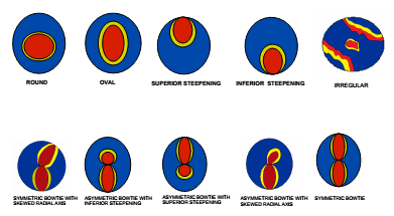
D. TOPOGRAPHIC PATTERNS
10 different topographical patterns have been described by Rabinowitz et al.They are:
 |
E. TOPOGRAPHIC MAPS:
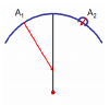
i) CORNEAL POWER MAP (AXIAL) : represents the corneal power at various points on the cornea in dioptric values with the constraint that all the centres of rotation must fall on the axis defined by the optical axis of the VKC.
 |
In this map localised changes in curvature is poorly represented.
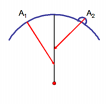
ii) TANGENTIAL MAP: or the instantaneous curvature map gives a better geographical representation because each point on the curvature has an independent radius of curvature. It represents localised changes and peripheral data better than axial maps. It is the best indicator of corneal shape but a poor indicator of corneal power
 |
iii) ELEVATION MAP: helps to identify localized elevations. Warm colors represent elevated areas above the reference sphere and cooler colors represent depressed areas.
iv) REFRACTIVE MAP: or the asphericity map takes into account spherical aberrations. It shows how the cornea refracts light. Aspherical cornea has cooler colors centrally and warm colors peripherally.It is useful to determine the optical zone of the RGP lens, and in performing refractive corneal surgery
v) IRREGULARITY MAP: it displays the distortion of the cornea with reference to a previous elevation map i.e a best fit spherocylindrical toric surface as reference sphere. It enables quick diagnosis of any corneal abnormality causing visual disturbances.
TOPOGRAPHIC DISPLAYS - ELEVATION BASED DEVICES
In these devices, the machine usually provides a composite printout display. The most common maps that are provided in the display include - the anterior elevation map, the posterior elevation map, the tangential power display, and the pachymetric map. In reading the elevation maps it is important to remember that the colors represent the elevation data. Any point on the cornea that is higher than the best-fit sphere will be shown as a peak - in the “hotter” colors, and any point that is lower than the best-fit sphere will be shown as a valley - in the “cooler” colors. This can initially lead to confusion when comparing these images with the power display maps of the Placido based devices, but with time, the differences become easier to understand.
 |
HOW TO READ A TOPOGRAPHIC MAP :
It is important to remember that despite the increasing sophistication of the devices used to measure and map the cornea - they essentially remain investigative tools and cannot be used as the sole basis for making a diagnosis. As with any investigation, they are used best and most optimally if the doctor has a good history of the ocular problem, and has performed a thorough clinical exam - not just of the cornea, but the entire eye - before resorting to corneal topography.
The findings of the topographic exam should be interpreted in light of the above findings to make a complete diagnosis of the problem, and the relevance of the corneal change towards the same - so that appropriate treatment can be instituted.
IN THE EXAM
1. Look at the basic data on the map - patient demography, eye, date of the procedure
2. Look at which eye is being examined
3. Look at the scale which is used for the color display
4. Look at the tangential map for an overview of the corneal picture
5. Look at the elevation maps - for the maximum elevation
6. Correlate the elevation maps for the anterior and posterior surfaces to see if the maximally
elevated maps match
7. Look at the pupil and its relevance to the corneal changes
8. Examine the pachymetric data and its correlation with the corneal maps
9. Look at the indices provided by the instrument - keratometric values, and the other
parameters described above
10.Try and match the corneal data provided with a list of possible diagnoses
Comment on the map given to you, using the above parameters. Do not provide a firm diagnosis after the above is done. Politely ask for a clinical history about the patient in question. If such is provided, then a diagnosis may be possible. If the examiner declines to provide you with such information, then it is best to provide only a differential diagnosis - based on the corneal changes noted. If asked for the reason for not providing a firm diagnosis, it is better to explain that the map only provides an idea of the corneal curvature changes that are present and does not provide a diagnosis - for example, a hyperopic corneal refractive procedure will produce a relative central corneal steepening that can mimic keratoconus; a central corneal scar can provide corneal flattening that can mimic a corneal refractive surgical procedure for myopia.
EXAM PREPARATION
It would be ideal to make a list of the various corneal conditions that can be asked in the exam - as topographic maps - this includes RK, PRK, and LASIK for myopia and hyperopia, penetrating keratoplasty, corneal ectasia, irregular corneas, normal maps, astigmatism - symmetric and asymmetric bowtie, forme fruste keratoconus, posterior keratoconus. Try and find atlases or online pictures of these conditions - both in Placido-based and Elevation based systems - and in different color scales - to help you prepare for the exam.